1.0 PURPOSE:
1.1 This instruction explains the procedure to assemble Moeller Mfg Click-Loc® lockrings on typical fitting ends, defines the required interfacing dimensions and assembly tooling and provides general information which may be useful. It is provided to assist the users in developing their own work instructions.
2.0 SCOPE:
2.1 This instruction is applicable to Moeller Mfg., (Cage 08244), part number SW31504 and SW31282 and similar lockrings. This instruction is for reference purposes only and is not a controlled document.
3.0 APPLICABLE DOCUMENTS:
3.1 The following links are included as part of this instruction:
Fitting End Dimensions
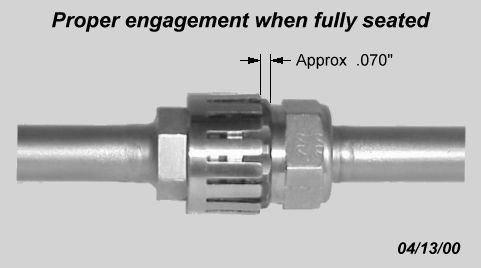
Proper Engagement
Lockring Removal
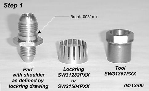
Step 1
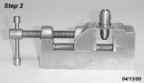
Step 2
Step 3
Step 4
Step 5
3.2 The following documents are referenced in this instruction:
AS4395
MS9197
MS9198
MS33514
SW31282
SW31504
SW31511
4.0 SYNOPSIS:
4.1 The lockrings are a component of a self-locking device for fluid fitting connections and similar components. The lockrings fit specially machined flared or flareless fitting ends functionally equivalent to typical design standards. The last two digits of the part number (i.e. SW31504P06) correspond to the size dash number (size identifier) of the fitting ends. The design standard fitting end (i.e. AS4395, MS33514) is supplemented by the addition of a shoulder immediately behind the thread relief. This shoulder is machined to a precision diameter and the SW31504 lockring is assembled on this diameter and retained by a controlled interference fit. The lockring locates against a suitable surface behind the shoulder to maintain the required axial position of the lockring relative to the end of the fitting end. The mating coupling nut incorporates a detented sleeve (ref. SW31511) or integral detents positioned such that when assembled with the specified ferrule and seated, the lockring will engage the detent area to approximately .130 inch leaving approximately .070 inch exposed. See Proper Engagement.The flexible beam “fingers” of the lockring act against the detents to generate a ratcheting-type prevailing torque that prevents the coupling nut from loosening.
5.0 PREPARATION:
5.1 The part fitting end, shoulder and locating surface must be machined as specified on the lockring drawing. See Fitting End Dimensions for an example of typical shoulder dimensions. The shoulder diameter should have a microfinish of Ra125 or better. For ease of assembly we recommend the shoulder diameter be held to the middle or low end of the specified tolerance range and the leading edge of the shoulder have at least a .003 inch edge break. See Step 1.
5.2 An assembly tool, SW31357 or equivalant, is required to assemble the lockring. If tool SW31357 is not available a functional substitute can be made drilling through and re-tapping a MS9197 or MS9198 coupling nut so that it has a full internal thread like an ordinary nut.
5.3 A suitable fixture is required to securely hold the part with the fitting end while assembling the lockring. This will be done by tightening the assembly tool to a torque level roughly equivalent to the in-service tightening torque of the actual mating part.
6.0 ASSEMBLY:
6.1 Apply a little grease or heavy oil to the threads and shoulder of the part on which the lockring is being assembled. Oil with a high film strength (i.e. STP) or a waxy oil (i.e. Safety-Draw 722) is recommended.
6.2 Mount part in fixture so that it is held securely and the shoulder is fully accessible. See Step 2. The picture shows a small machinists’ vise being used to hold the part. A fixture specifically designed to fit the part would be much better.
6.3 Put lockring on over threads, with the fingertips pointing out toward the fitting end.
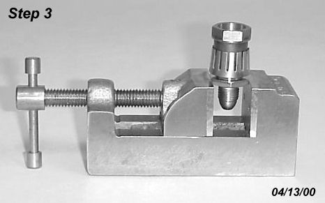
6.4 Screw assembly tool SW31357 onto fitting end and finger tighten. This should locate the lockring squarely against the leading edge of the shoulder. See Step 3.
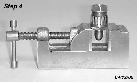
6.5 Use a 6-point socket wrench and ratchet and tighten assembly tool forcing lockring onto shoulder. Continue to tighten tool until lockring is fully seated. See Step 4.
6.6 Loosen assembly tool and unscrew. Once loosened, tool should easily unscrew from the fitting end (free running, no significant drag).
6.7 Visually inspect to be sure lockring is fully seated (.005 inch maximum gap). See Step 5.
7.0 ADDITIONAL NOTES:
7.1 The interference fit for lockrings is typically .002 – .004 inch. High-limit interference fits will require a substantial torque be applied to fully seat the lockring. If this is causing difficult assembly, the lockrings can be pre-heated to 450°F maximum and/or the part can be cooled with dry ice to reduce the assembly forces.
7.1 If the lockring gets damaged by any cause it can be removed by using a small gear or bearing puller. The fitting end must be protected if using a puller. A MS9197 or MS9198 nut can be used for a protector. Engage nut 4 turns prior to tightening puller. For larger sizes, a washer must also be used to prevent the puller bolt from entering the hole in the nut and possibly damaging the fitting end. See Lockring Removal.
Moeller Aircraft Division Homepage
issued 04/20/00 (similar to MP-61)
format updated 05/01/00