LOCKRING INSTALLATION INSTRUCTIONS
1.0 PURPOSE:
1.1 This instruction explains the procedure to install Moeller Mfg Click-Loc® lockrings on typical turnbuckle-type parts, defines the required interfacing dimensions and installation tooling and provides general information which may be useful. It is provided to assist the users in developing their own work instructions.
2.0 SCOPE:
2.1 This instruction is applicable to Moeller Mfg., (Cage 08244), part number SW31302 and similar lockrings. This instruction is for reference purposes only and is not a controlled document.
3.0 APPLICABLE DOCUMENTS:
3.1 The following links are included as part of this instruction:
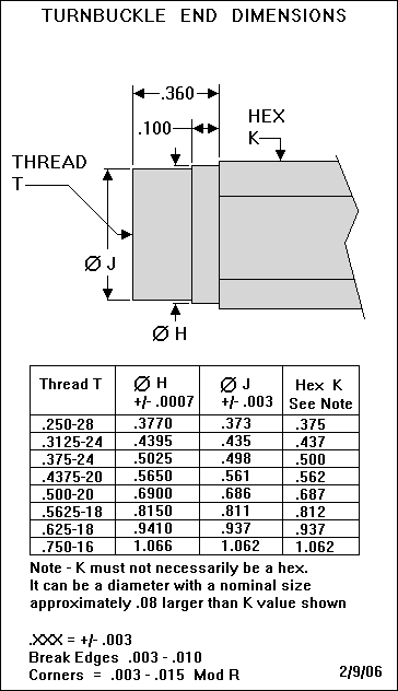
Turnbuckle End Dimensions
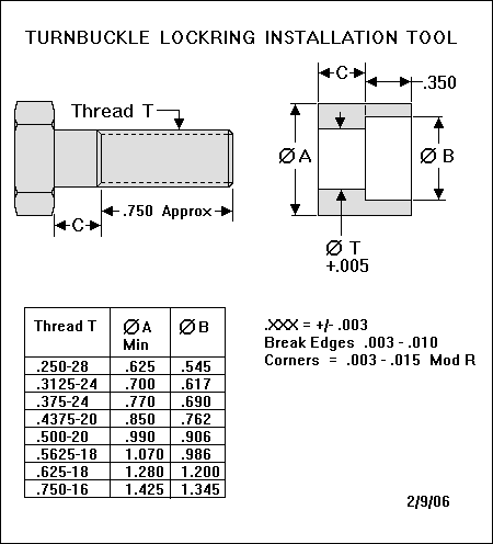
Turnbuckle Lockring Installation Tool
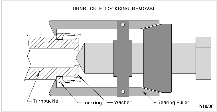
Turnbuckle Lockring Removal
3.2 The following documents are referenced in this instruction:
SW31302
SW31311
SW31419
4.0 SYNOPSIS:
4.1 The lockrings are a component of the Click-Loc® self-locking device for turnbuckles and similar jam nut locked applications. The lockring is installed by a controlled interference fit over a machined diameter on the end of the turnbuckle. It locates against a suitable surface behind the machined diameter to maintain the required axial position of the lockring relative to the end of the turnbuckle. The mating jam nut (ref SW31311/SW31419) incorporates integral detents positioned such that when assembled with the turnbuckle, the lockring will engage the detent area to approximately .100 inch. The flexible beam “fingers” of the lockring act against the detents on the jam nut to generate a ratcheting-type prevailing torque that prevents the jam nut from loosening.
5.0 PREPARATION:
5.1 The turnbuckle end must be machined as specified on the lockring drawing. See Turnbuckle End Dimensions for an example of typical dimensions. The machined diameter should have a microfinish of Ra125 or better. For ease of installation we recommend the machined diameter be held to the middle or low end of the specified tolerance range and the leading edge of the machined diameter have at least a .003 inch edge break.
5.2 A tool is required to install the lockring. The tool consists of a bolt with threads to fit the turnbuckle and a bushing to help guide the lockring and maintain squareness during installation. See Turnbuckle Lockring Installation Tool for an example of typical bolt and bushing dimensions.
5.3 A suitable fixture is required to securely hold the turnbuckle while installing the lockring. The fixture must be capable of resisting torque roughly equivalent to the normal tightening torque for the jam nut. If the turnbuckle has a hex drive then a machinist’s vise may serve as a suitable assembly fixture.
6.0 INSTALLATION:
6.1 Apply a light coat of oil to the threads and machined diameter of the turnbuckle. Oil with a high film strength (e.g. STP) or a waxy oil (e.g. Safety-Draw 722) is recommended.
6.2 Mount the turnbuckle in fixture so that it is held securely and the machined diameter is fully accessible.
6.3 Put lockring on over the machined diameter with the fingertips pointing outward.
6.4 Fit the installation tool bushing over the lockring and screw the bolt into the turnbuckle and finger tighten. This should locate the lockring squarely against the leading edge of the machined diameter.
6.5 Use a 6-point socket wrench and ratchet and tighten the installation tool bolt forcing the lockring over the machined diameter. Continue to tighten the bolt until the lockring is fully seated.
6.6 Loosen the installation tool bolt. Once loosened, the bolt should easily unscrew from the turnbuckle and the bushing should slip off the lockring with no noticeable drag.
6.7 Visually inspect to be sure lockring is fully seated (.005 inch maximum gap) and there is no visible damage to the lockring or turnbuckle.
7.0 ADDITIONAL NOTES:
7.1 The interference fit for lockrings is typically .002 – .004 inch. High-limit interference fits will require a substantial torque be applied to fully seat the lockring. If this is causing difficult assembly, the lockrings can be pre-heated to 450°F maximum and/or the part can be cooled with dry ice to reduce the assembly forces.
7.2 If the lockring gets damaged by any cause it can be removed by using a small gear or bearing puller. The end of the turnbuckle threads must be protected when using a puller. A common flat washer with a hole slightly smaller than the turnbuckle thread size makes a suitable protector. Make sure the flat washer is sitting against the end of the turnbuckle (not the fingertips) before tightening the puller. See Turnbuckle Lockring Removal for a picture of the correct position of the puller and washer.
Moeller Aircraft Division Homepage
issued 02/10/2006